


Working Principle
Valve Closing Mode
The valve closes when the pilot system directs line pressure into the control chamber (the area above the diaphragm). This pressure, combined with the spring force, creates a downward force greater than the upward force of the line pressure. The resulting net force pushes the diaphragm downward, closing and sealing the valve.
Valve Opening Mode
To open the valve, the pilot system vents the control chamber, releasing the pressure above the diaphragm. With the closing pressure removed, the upstream line pressure exerts a stronger upward force than the spring’s downward force, lifting the diaphragm and fully opening the valve.
Modulation Mode
Modulation occurs when the valve is held in a partially open position to regulate pressure or flow. The pilot system achieves this by continuously adjusting the pressure in the control chamber. By balancing the upward line pressure against the combined downward forces of the chamber pressure and spring, the diaphragm maintains an intermediate position, allowing the valve to sustain a desired downstream pressure or flow rate.
ADVANTAGES
Autonomous, Energy-Free Operation: Operates solely on the line’s inherent hydraulic pressure—no external electricity or pneumatic supply required. This simplifies installation, minimizes operating costs, and ensures continuous functionality even during power outages.
Versatile Multi-Function Control: Performs multiple functions such as on/off control, pressure reduction, and flow modulation within a single compact unit, offering exceptional flexibility in system design.
Stable Downstream Pressure: The precision pilot system maintains a constant, desired outlet pressure regardless of fluctuations in upstream pressure or flow rate, ensuring protection for downstream components.
Robust Cast Body Construction: Constructed from heavy-duty cast materials for long-lasting performance and reliability under high-pressure and demanding operating conditions.
Built-in Safety Features: Automatically shuts off in the absence of line pressure, preventing potential damage from dry-run conditions and safeguarding pumps and connected systems.
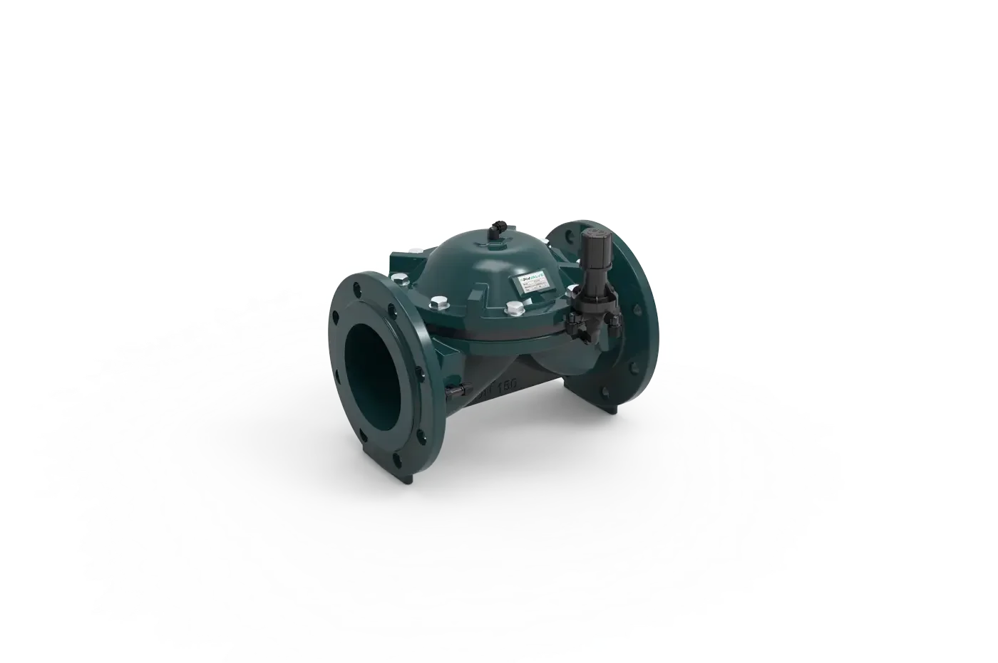
Quick Pressure Relief Control Valve
Unwavering Control for Critical Systems.
Precise and reliable control in complex water systems is ot a luxury, but a ecessity. Our Cast Iron Hydraulic Control Valves are designed to provide this precision by operating autonomously using only the energy of line pressure. From simple on/off functions to complex pressure regulation and flow modulation, these valves form the versatile and robust core of your system and are ideal for demanding applications in irrigation, municipal water lines and industrial processes.
GENERAL FEATURES
These valves are a critical safety element against sudden excessive pressure surges.
It opens instantly to protect the system when pressure exceeds the set value.
Thanks to its hydraulic control mechanism, it ensures fast opening and controlled closing.
This prevents damage caused by water hammer and sudden pressure spikes.
It provides drip-tight closing and can also be used as a high-pressure warning valve.
| Valve Body Material | GGG40 |
| Diaphragm Material | Natural Rubber |
| Minimum Working Pressure | 1 bar ; 14,5 Psi |
| Maximum Working Pressure | 16 bar ; 232 Psi |
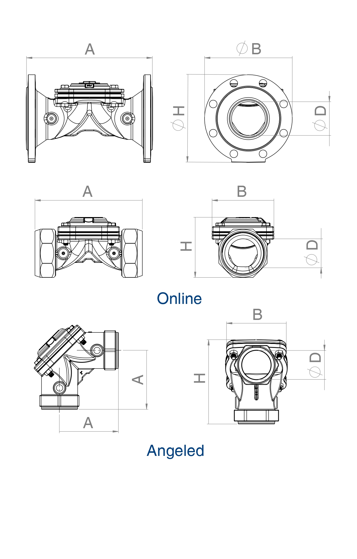
| Code | Giriş/Çıkış (D) | Connection Type | Valve Type | Dimensions (mm) | Max. Flow Rate | Çalışma Basıncı Aralığı | |||||
|---|---|---|---|---|---|---|---|---|---|---|---|
| İnç | DN | A | H | B | m³/h | GPM(US) | Bar | °C (°F) | |||
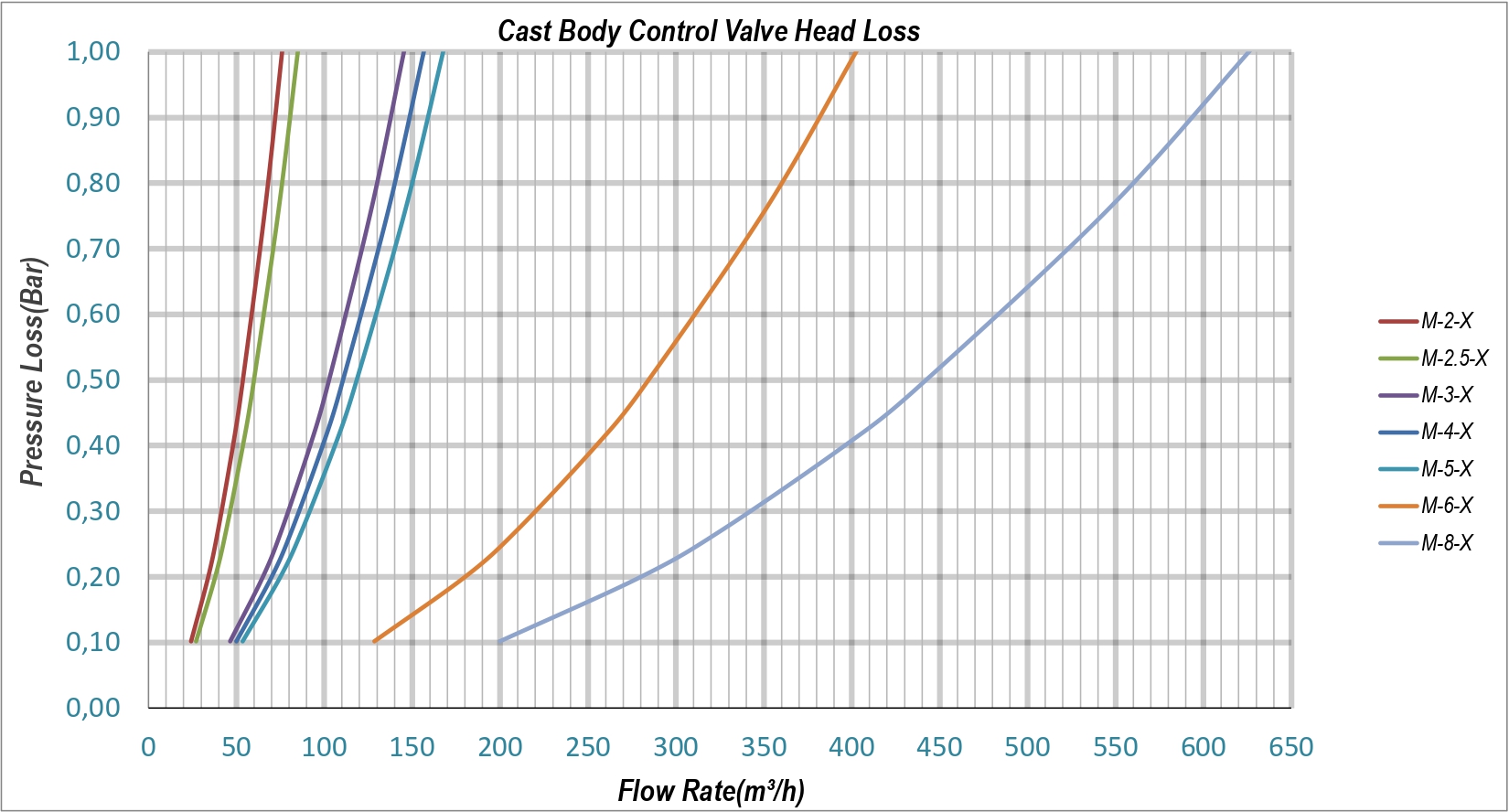
| M-2-X | 2 | 50 | Threaded | Angled | 105 | 150 | 107 | 40 | 176 | 1-16 | 60(140) |
| M-2-X | 2 | 50 | Threaded | Online | 181 | 101 | 107 | 40 | 176 | 1-16 | 60(140) |
| M-2.5-X | 2 1/2 | 65 | Threaded | Online | 199 | 117 | 107 | 50 | 220 | 1-16 | 60(140) |
| M-3-X | 3 | 80 | Flanged | Online | 278 | 200 | 205 | 80 | 352 | 1-16 | 60(140) |
| M-4-X | 4 | 100 | Flanged | Online | 330 | 223 | 223 | 90 | 396 | 1-16 | 60(140) |
| M-5-X | 5 | 125 | Flanged | Online | 373 | 260 | 260 | 90 | 396 | 1-16 | 60(140) |
| M-6-X | 6 | 150 | Flanged | Online | 401 | 303 | 297 | 90 | 396 | 1-16 | 60(140) |
| M-8-X | 8 | 200 | Flanged | Online | 561 | 335 | 335 | 105 | 462 | 1-16 | 60(140) |