


Cleaning Process
The cleaning process is triggered either by elapsed time or a differential pressure threshold. Differential pressure results from particle accumulation on the screen surface, which restricts water flow. This pressure difference—an undesirable condition—is resolved by the cleaning cycle. The filter is programmed to automatically start the cleaning process once the user-defined differential pressure value (recommended at 0.5 bar) is reached, thereby restoring ormal operation. When the drain valve opens, a strong vacuum effect is created inside the filter, drawing debris from the screen surface. This suction helps the ozzles effectively remove particles from the screen and discharge them from the system. Once the process is complete, the cleaning collector automatically returns to its original position, and ormal filtration resumes. During backwashing, the filtering process continues. To ensure efficient operation, the inlet pressure should ot be less than 2 bar (29 psi) during backwashing
Working Principle
Water enters through the inlet line and flows toward the outlet line of the filter. During the cleaning process, the drain line serves as the discharge path for accumulated contaminants. The piston rod is responsible for linear motion, allowing the ozzles to scan the surface of the filter screens during cleaning. When water enters the system, it first passes through a coarse screen for preliminary filtration, followed by a fine screen for further filtration. As water flows through the fine screen, particles are retained on its surface. During the cleaning cycle, these particles are suctioned by the ozzles and transported to the cleaning collector. The turbine chamber is connected to the atmosphere and houses the turbine, which generates rotational motion to drive the ozzles. The combination of the linear motion of the piston rod and the rotational mo - tion from the turbine ensures complete coverage of the screen surfaces. The hydraulic piston drives the piston rod. Activation of the piston and the opening of the drain valve occur simultaneously.
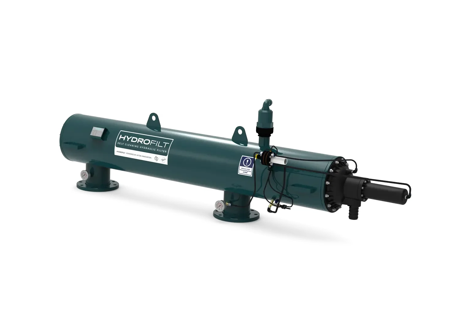
HDF Series - Horizontal Self-Cleaning Hydraulic Filters
ADVANTAGES


Stop Wasting Resources on Filtration.
The HDF series is your definitive upgrade to a hands-off, zero-energy solution. Its intelligent hydraulic system eliminates manual labor and provides a continuous supply of clean water without stopping. Built for easy accessibility and featuring intrinsic safety, it’s the smart investment to cut costs, save time, and boost reliability.
GENERAL FEATURES
| Body Material | S235JR / SS304L / SS316L |
| Screen Material (Internal Kit) | SS304L, PA6GFR30 |
| Maximum Working Pressure | 10 bar; 145 Psi |
| Minimum Working Pressure | 2.5 bar; 36 Psi |
| Maximum Working Temperature | 60 °C; 140 °F |
| Back Washing Time | Pressure Difference Setup |
| Control System | Hydraulic |
| Filtration Sensitivity | 20-2000 μ (micron) |
| Painting Method | Electrostatic Powder Coating |
| Paint Coating Material | Epoxy-Polyester |

| CODE | Inlet/Outlet | A | B | L1 | L | D | F | Drain Flow Rate | Main Flow Rate | Filtration Area cm² |
Nozzle Qty. |
Screen Qty. |
Weight kg |
|||
|---|---|---|---|---|---|---|---|---|---|---|---|---|---|---|---|---|
| Inch | DN | mm | mm | mm | mm | Inch | Inch | L/s | GPM(US) | m³/h | GPM(US) | |||||
| HDF/CHDF104 | 4 | 100 | 500 | 287 | 1020 | 1600 | 10 | 2 | 3,3 | 53 | 120 | 528 | 2634 | 2 | 4 | 71 |
| HDF/CHDF104S | 4 | 100 | 600 | 287 | 1220 | 1800 | 10 | 2 | 4,1 | 66 | 140 | 616 | 3951 | 3 | 6 | 81 |
| HDF/CHDF105 | 5 | 125 | 600 | 287 | 1220 | 1800 | 10 | 2 | 4,1 | 66 | 150 | 660 | 3951 | 3 | 6 | 83 |
| HDF/CHDF105S | 5 | 125 | 900 | 287 | 1530 | 2110 | 10 | 2 | 5 | 79 | 160 | 704 | 5268 | 4 | 8 | 89 |
| HDF/CHDF106 | 6 | 150 | 900 | 287 | 1530 | 2110 | 10 | 2 | 5 | 79 | 180 | 792 | 5268 | 4 | 8 | 93 |
| HDF/CHDF126S | 6 | 150 | 1100 | 312 | 1922 | 2510 | 12 | 2 | 6,6 | 106 | 220 | 968 | 7902 | 6 | 12 | 130 |
| HDF/CHDF128 | 8 | 200 | 1100 | 312 | 1922 | 2510 | 12 | 2 | 6,6 | 106 | 320 | 1408 | 7902 | 6 | 12 | 133 |
| HDF/CHDF1210 | 10 | 250 | 1100 | 312 | 1922 | 2510 | 12 | 2 | 6,6 | 106 | 380 | 1672 | 7902 | 6 | 12 | 142 |